
R740D 20-3000 PSIG Baratron® Differential Capacitance Manometers with Trip Relays
R740D 20-3000 PSIG Baratron® Differential Capacitance Manometers with Trip Relays
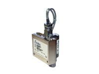
The R740D High-Pressure Baratron® Gauge Capacitance Transducer is a rugged, industrial-grade pressure and vacuum transducer with superior accuracy, repeatability, and long-term signal stability. It has a standard 0-10 VDC analog output signal and two (2) independently-adjusted electromechanical trip relays that can be used to switch external components such as pumps, valves, and other equipment.
- 10 Torr (13 mbar) to 3000 PSI (204 bar) ranges with ±1% of reading accuracy
- 0-10 VDC analog output proportional to differential pressure
- Two independently-adjusted trip point relays
- All-welded Inconel® sensor construction allows for use with most corrosive media
- Self-contained sensor and signal conditioner in a compact and rugged enclosure See All Features
Configuration Options
The following options are available for R740D Baratron® Differential Pressure Transducers
Ordering Code Example: R750D13TCE2GG
| Configuration Option | Option Code |
|---|---|
| R740D Differential Capacitance Manometer | R740D |
Range Full Scale |
|
| 20 psig | 21P |
| 50 psig | 51P |
| 100 psig | 12P |
| 200 psig | 22P |
| 250 psig | RDP |
| 500 psig | 52P |
| 1000 psig | 13P |
| 2000 psig | 23P |
| 3000 psig | 33P |
Fittings |
|
| 0.5 in. OD tube | BA |
| 1/4 in. OD weld stub | BB |
| 4 VCR male | CB |
| 4 VCR female | CD |
| 8 VCR female | CE |
| 8 VCO female | DA |
| 0.25 in. NPT female | FA |
| 0.25 in.NPT male | FB |
| 0.125 in. NPT female | FE |
| 0.125 in. NPT male | FF |
| NW16 ISO-KF | GA |
| 1.33 in. OD CF | HA |
Analog Output |
|
| 0-10 VDC | 2 |
Accuracy |
|
| 1.0% of Reading | G |
Trip Point Setting |
|
| Relays activate above trip points | G |
| Relays activate below trip points | S |
Specifications
- TypeVacuum/pressure Transducer
- Measurement TypeDifferential
- Full Scale Pressure Ranges20-3000 PSI (1.4 to 204 bar)
- Accuracy±1% of Reading
- Resolution±0.01% of Full Scale
- Repeatability±0.1% of Reading
- Analog Output0 to 10 VDC into >10 k Ω load
- Electrical Connector15-pin D-subminiture
- Zero Temperature Coefficient0.02% of Full Scale/°C
- Span Temperature Coefficient0.04% of Reading/°C
- Volume4.7 cc
- Power Requirements±15VDC (± 5%) @ 35 mA (max)
- Factory Default Trip Relay SettingsTrip Relay A energizes below 55% of full-scale range, and Trip Relay B energizes above 55% of full-scale range.
- Relay SpecificationsTwo independently-adjusted DPDT contacts adjustable between 0.5% and 100% of FS. Relays are UL listed and rated at 1.0 amps @ 30 VDC or 0.3 amps @ 30 VAC.
- Weight1.0 lbs (0.4 kg)
- ComplianceCompliant with EMC Directive 2004/108/EC
Compliant with Directive 2002-95-EC
Features
Percent of Reading Accuracy
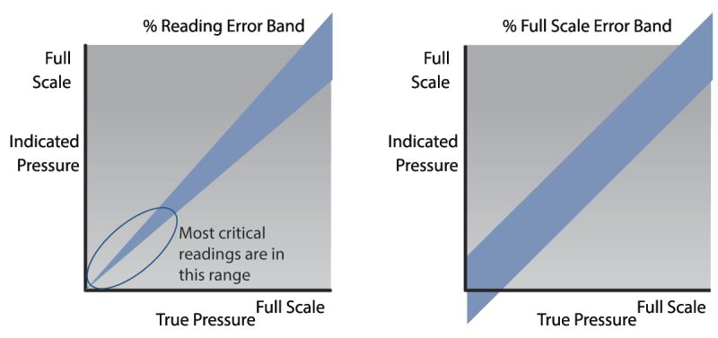
Accuracy is specified as a percent of Reading, not Full Scale, as seen in some of the lower performance devices. Percent of Reading accuracy provides you with an even more accurate output signal in the lower scale of the pressure range, where it is needed most.
Differential Pressure Measurement
These capacitance manometers are referenced to local atmospheric pressure and measure the difference between the measurement side (Px) and the reference side (Pr) of the diaphragm. Applications include air and gas flow measurements for filters and analytical systems, downstream pressure control in thin film processing systems, and automated leak testing systems.
Inconel® and Incoloy® Construction Wetted Surfaces
These pressure transducers feature Inconel® and Incoloy® nickel alloy construction of the pressure sensor allowing it to operate without damage in virtually any chemical environment, including halogens, deionized water and steam, and ozone. The sensor is fully welded with no intermediate brazing or joining materials.
0 to 10 VDC Proportional Analog Output
These Baratron® capacitance manometers feature a high-level 0-10 VDC analog output signal that is linear with pressure. This analog output can be interfaced with an MKS pressure controller, an MKS power supply/display instrument, or any instrument that meets these requirements.
Two Adjustable Process Trip Point Relays
These pressure transducers feature two user adjustable process trip point relays, each with an adjustment range from 0.5% to 100% of Full Scale or voltage equivalent 0.05 to 10 VDC. The relays are UL listed and rated at 1.0 amps @ 30 VDC or 0.3 amps @ 30 VAC. The trip points are factory set at 55% of full scale with relay A energizing below that level and relay B energizing above the trip point.
15-pin Type "D" Pin-Outs
| Pin | Description |
|---|---|
| 1 | Relay Contact A, N.O. |
| 2 | Pressure Output |
| 3 | Reserved |
| 4 | Reserved |
| 5 | Power Return |
| 6 | -15 VDC |
| 7 | +15 VDC |
| 8 | Relay Contact A, N.C. |
| 9 | Relay Contact B, N.C. |
| 10 | Trip Point A, Setting |
| 11 | Trip Point B, Setting |
| 12 | Pressure Return |
| 13 | Relay contact B, N.O. |
| 14 | Relay Contact B, Common |
| 15 | Relay contact A, Common |
Accessories
Compatible Cables
| Compare | Description | Drawings, CAD & Specs | Avail. | Price | ||
|---|---|---|---|---|---|---|
 | RCB700S-1-10 | |||||
| RCB700S-21-10 | |||||
| RCB700S-29-10 | |||||
| RCB700S-34-10 |
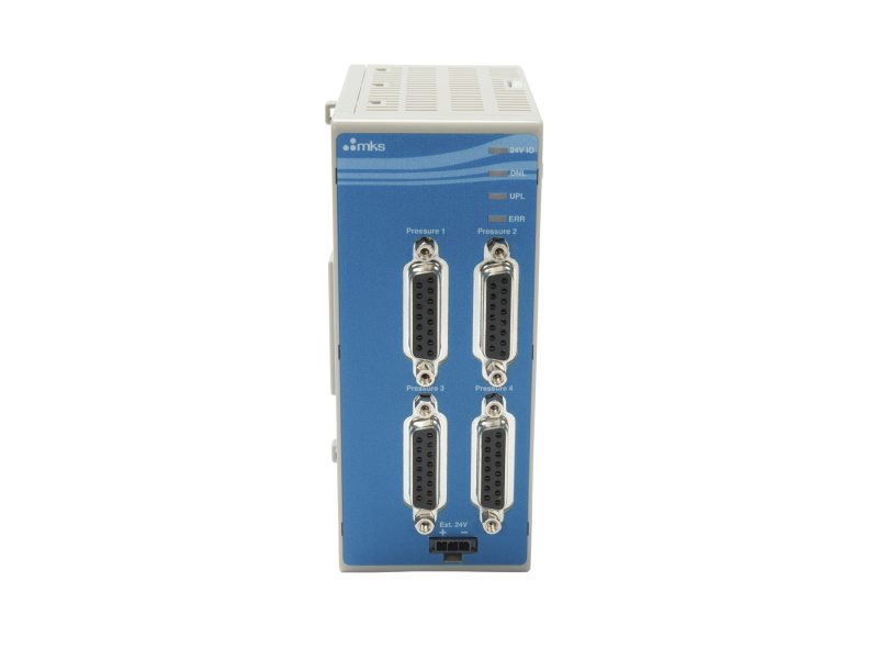
Power Supplies and Displays
| Compare | Description | Drawings, CAD & Specs | Avail. | Price | ||
|---|---|---|---|---|---|---|
 | AS11900G-03 | |||||
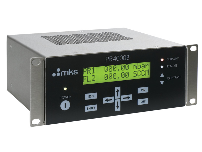 | PR4000BF2V2 | |||||
| PR4000BF2V3 | |||||
| PR4000BF5V2 | |||||
| PR4000BF5V3 | |||||
| PR4000BS2V3 | |||||
| PR4000BS2V2 | |||||
 | PDR2000AO |